Finally got my shit together and posted pics. Also finally got some work done. :-P
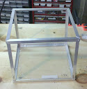
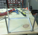
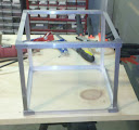
The finished frame I forgot to take a picture of. I think if I did this again I'd use 3/4" angle after all, because this one is a touch flimsy, but it should be sturdy enough once I install the drive mounts and such.
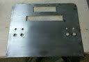
For the front panel, I took a side panel from that old case I posted pics of in the beginning and laid out my piece. I used the existing bottom edge of the panel for the bottom edge of my front, and drew the piece with about 1/2" of space to fold the other edges back,

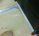
Then I cut it out with the nibbler and folded the edges under. Nibbling took a long time and a fair bit of sweat. The folds aren't perfect, but they're acceptable; best I could do without a bending brake. I will definitely be getting a brake if I do another project like this, though.
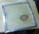
I figured some rough sizes for the VFD and DVD openings, then added to them the thickness of the chrome molding. I laid these out sometime during the week, after work one night. On Friday, I cut those out with the nibbler. Later, I went out and picked up a switch (just one for now, to get measurements) and some LED holders, and drilled out their locations. The only thing left to mark off is the plasma ball, and I don't have that to measure yet. So, I moved onto the sanding.
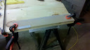
Saturday: I tried several different sanding methods to no avail. Hand sanding got some metal exposed, but even applying heat beforehand, it was way too much work. The palm sander just made paint dust and never actually took it off. I was about to give up and paint the fucking thing, when I remembered my detail sander. I gave it a shot, and it was working! The extra-coarse sheet is what did the trick, I think; I only had one of those, so I was lucky to make it through before it wore out.
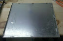
Unfortunately, my bending and cutting left a couple of small divots in the front face, and I knew I'd never get those sanded evenly. Oh well; most of it is at the edges, so it shouldn't be too visible once the whole thing is together. The other spots will hopefully just make it look a little used/aged.
To get the remaining paint out of the deeper spots, I used a Dremel wire wheel. Rather than get out the Dremel, I popped it in my drill, and it worked very well, but this is what it looked like when I was done. Glad I have more of those!
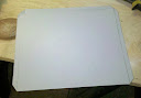
After that, I block sanded it with 100-grit to get the grain looking right, and went over it again with a wire brush. I polished it a bit with some rubbing compound, and the end result is pretty decent. You'll see that in the next pics, although it needed to be cleaned up again by then. It should look pretty good when I'm ready to assemble.
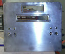
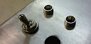
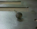
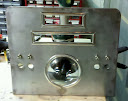
The chrome molding went on next. It didn't turn out as well as I'd hoped. I might try something else, or at least come up with something to cover the corner seams. That molding is a modder's friend for covering roughly cut edges: it's flexible, self-adhesive, and cheap. However, it doesn't do well on 90-degree corners, and always leaves the seams to deal with. It's perfect for a blowhole, though, especially if you're putting a gril over the top of it (one of the screwhole legs will cover the seam nicely). Next were the LED holders, which I ended up liking even better than my original lamp lens idea; they really look like they belong there, I think. I added the one switch I bought for the pictures. In the closeup of the LED holders, you can see the grain on the stainless a little better, too.
Today, I'm either going to work on the drive mounts or the outer shell. Probably the shell, so I can get to painting before the warm weather is over.

 Step 1: Measure and lightly score where your break will be, and line up that score line with the edge of your workbench (or a good, straight board edge). Place a board on top, also lined up with the score line. Clamp it down tight. It's best to have the scrap end outside, so that your desired piece is protected. When you break, if it happens to stray from your score lines, it will happen outside the edge of the board.
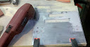
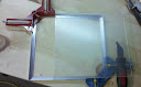
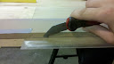 Step 2: Score deeply along that line. I got this handy little tool for it, but a sharp razor blade works just as well. Make sure it goes quite deep, and that you go all the way to the edges of your piece. If you skimp at the edges, you'll have some filing/Dremel-ing to do, and unless you're really good, it will probably never be quite even.
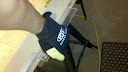 Step 3: You only see one of my hands here, but you'll want to use both hands. Place your hands in positions at which the pressure will be evenly distributed along the break line. I find it easiest to have the heels of my hands closer to the score lines, with my fingers curling under the edge of the piece. Now, start to apply pressure, then push down sharply. I wore the gloves here to get a good grip, since I was breaking off a pretty small piece.
 You should get a lovely, clean break every time. The key is the board on top applying pressure. I always hear people say you just need to apply even pressure on both sides, but for longer breaks, it will still crack outside your score line. If your piece is about 6" wide or less, you can probably get away without the board and use one hand on each side of the line.